What is the relationship between elastic constants E, G and K?
Consider the following statement :
The thermal stress is induced in a component in general, when
(1) A temperature gradient exists in the component.
(2) The component is free from any restraint.
(3) It is restrained to expand or contact freely.
Which of the above statements are correct?
If the ratio G/E (G = Rigidity modulus, E = Young’s modulus of elasticity) is 0.4, then what is the value of the Poisson ratio?
What is the materials which show direction dependent properties, called?
In a tensile test, near the elastic limit zone
A bar of copper and steel form a composite system. They are heated to a temperature of 400C.What type of stress is induced in the copper bar?
The necessary and sufficient condition for a surface to be called as a free surface is
The components of strain tensor at a point in the plane strain case can be obtained by measuring longitudinal strain in following directions
The number of elastic constants for a completely anisotropic elastic material is
The stress-strain diagram for two materials A and B is shown below:
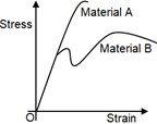
The following statements are made based on this diagram
(l) Material A is more brittle than material B
(ll) The ultimate strength of material B is more than that of A
With reference to the above statements, which of the following applies?
In a linear elastic structural element
The principle of superposition is use in structural computations when:
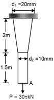
A tapered circular rod of diameter varying from 20 mm to 10 mm is connected to another uniform circular rod of diameter 10mm as shown in the following figure. Both bars are made of same material with the modulus of elasticity, MPa. When subjected to a load the deflection at point A is ______mm.
A box of weight 100 kN shown in the figure is to be lifted without swinging. If all the force are coplanar, the magnitude and direction of force F w.r.t. axis is


Find shear force, moment and axial stress at A. Assume pully to be frictionless.
A rigid bar is suspended by three rods made of the same material as shown in the figure. The area and length of the central rod is 3A and L, respectively while that of two outer rods are 2A and 2L, respectively. Of a downward force on the rigid bar, the forces in the central and each of the outer rods will be

Match List – I (Type and position of load on cantilever) with List – II (Shape of bending moment diagram for cantilever) and select the correct answer using the codes given below the lists:-
|
List-I |
List-II |
|
A. Carrying linearly varying load from zero at its free end and maximum at the fixed end. |
1. Parabola |
|
B. Subjected to uniformly distributed load. |
2. Rectangle |
|
C. Carrying concentrated load at its free end. |
3. Cubic Parabola |
|
D. Free end is subjected to bending moment. |
4. Triangle |
The bending moment diagram of the beam shown in the figure below is

The BMD and SFD for a beam are shown below in figure I and II. The corresponding Loading diagrams would be-


A simply supported beam is loaded as shown in the given figure. The Bending moment at point E would be-

Which one of the following statement is correct?
A simply supported beam is shown in the given figure.

The corresponding SFD and BMD would be –
A beam’s SFD and BMD are shown in figure – I and II.

The corresponding load diagram will be -
Two people weighing W each are sitting on a plank of length “L” floating on water atfrom either end. Neglecting the weight of the plank, the bending moment at the centre of the plank is
A loaded beam PQRS is shown in the given figure.

The magnitude of support reaction at R will be zero if the value of Load “W” is
