A GaAs LED is operating at 300k. Find the of the radiated light in lm.(given Eg at 300k=1.4ev)
Which of the following is an example of electroluminescent device?
The wavelength beyond which photo-electric emission cannot takes place is called
Optocoupler is a combination of
The reverse current in the photodiode is due to?
The Gun diode is made of
Which type of doping does ESAKI diode has?
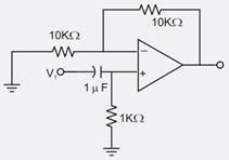
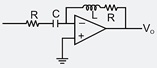
The op-amp circuit shown is the figure is a filter the type of filter & its cut-off frequency one respectively.
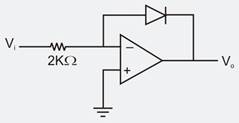
In the op-amp circuit shown, assume that the diode current follows the equation for Vi = 2V, V0 = V01 and for Vi = 4 V, V0 = V02, the relationship b/w V01 & V02 is
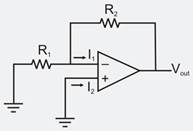
In the circuit shown, the op-amp has finite input impedance, infinite voltage gain and zero input offset voltages. The output voltages Vout is
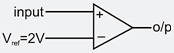
If the input to the ideal comparator shown in the figure is sinusoidal signal of 8v (peak to peak) without any DC component, then the o/p of the comparator has a duty cycle of.
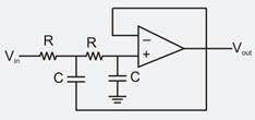
The op-Amp shown in fig. below is ideal. R = the phase angle between v0 and vi at w= is
Rf = 8, R1= 2 and A = 45
The circuit in the figure is a
The first domain pole encountered in the frequency response of a compensated op -amp is approximately at.
Which of the following are the non-linear applications of op-amp?
1. Current to voltage converter
2. Comparator
3. Peak detector
4. Limiter
