Consider the following standard symbols for two-port parameters:
1. h12 and h21 are dimensionless.
2. h11 and B have dimensions of ohms.
3. BC is dimensionless.
4. C is dimensionless.
Which of the above are correct?
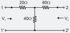
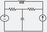
For the two-port network, the impedance parameter matrix is
A, B, C and D represent the transmission parameters of a two-port network. When is the network reciprocal?
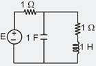
A series RLC circuit has a bandwidth of 300 rad/s at a resonant frequency of 3000 rad/s when excited by a voltage source of 100 V. The inductance of the coil is 0.1 H. The value of R and the voltage across C are, respectively
Consider two nodes A and B connected by an impedance of j5 . If the voltages at nodes A and B are V and V respectively, the real power that can be transferred from node A to B is
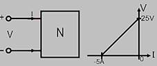
The voltage-current relationship feeding the network N is shown in the below figure. The Thevenin’s equivalent of network N will have VTH and RTH as
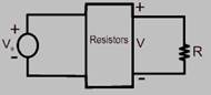
In the circuit shown below, for different values of R, the values of V and I are given, other elements remaining the same
When , V = 5 V
When ,
When , the value of V is given by
The linear network as shown below has only resistors. If and ; V is found to be 80 V. when and . Then the value of V when , is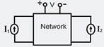
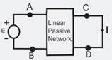
For the circuit shown in the given figure, when the voltage E is 10 V, the current I is 1 A. If the applied voltage across terminal C-D is 100 V, the short circuit current flowing through the terminal A-B will be
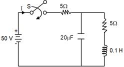
The network shown below is initially at rest. What is the initial current when the switch S is closed at t = 0?
Consider the following circuit:
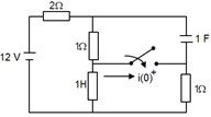
The circuit shown above is in steady state before closing the switch. What is the current through the switch if the circuit is closed at t = 0?
The graph associated with an electrical network has 7 branches and 5 nodes. The number of independent KCL equations and the number of independent KVL equations, respectively, are
The number of chords in the graph of the given circuit will be
An air-cored solenoid of 250 turns has a cross-sectional area A = 80 cm2 and length l = 100 cm. The value of its inductance is
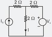
For the circuit shown below, the value of Vs is 0 when I = 4 A. The value of I when Vs = 16 V, is
The figure shows a network in which the diode is an ideal one.
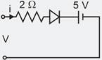
the terminal v-I characteristics of the network is given by
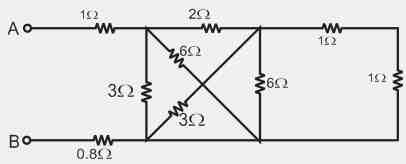
The equivalent resistance between the terminals A and B is ………..
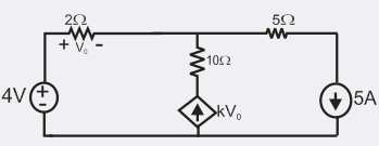
In the given circuit, the parameter k is positive, and the power dissipated in the resistor is 12.5 W. The value of k is….
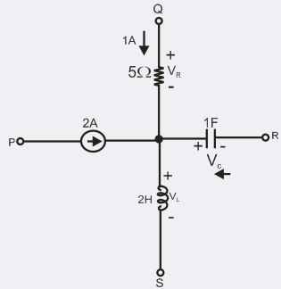
A segment of a circuit is shown in figure VR = 5 V, VC = 4 sin2t. The voltage VL is given by
If the power dissipated in the circuit shown below is 8 W, then the value of E will be