Which of the following equations satisfies the j K flip-flop truth table?
A 4-bit modulo-16 ripple counter uses J K flip-flops. If the propagation delay of each F.F is 50ns, the maximum clock frequency that can be used is equal to.
The circuit given below is a
A 4-bit ripple counter and a 4-bit synchronous counter are made using flip-flops having a propagation delay of 10ns each. If the worst case delay in the ripple counter and the synchronous counter be R and S respectively then.
The number of unused states in a 4-bit Johnson Counter is
Which of the following measurements can be done using a counter?
1. Pulse duration
2. Interval between two pulses.
3. Amplitude of the pulse.
4. Rise time of pulse.
Select the correct answer from the codes given below.
In a sequential circuit, the output at any instant of time depends.
The character equation of the T flip-flop is given by.
The highest speed counter is
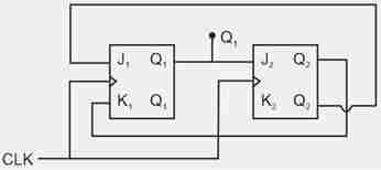
The outputs of the two flip-flops Q1, Q2 in the figure shown are initialized to 0, 0 the sequence generated at Q1 upon application of clock signal is.
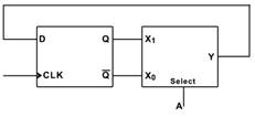
The state Transistor diagram for the logic circuit shown is
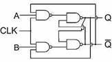
Consider the given circuit
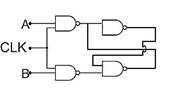
In this circuit, the race around.
A 3-variable truth table has a high output for the inputs: 010,011and110, the Boolean expression for sum of product (sop) can be written as.
The given figure shows a NAND gate with input waveforms A and B
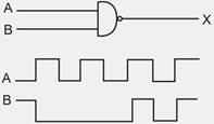
The correct output waveform x of the gate is
The inverter 74 AL S01 has the following specification.
IOH max=-0.4mA, IOL max=8mA
IIH max =20μA ,IIL max=-0.1mA
The fan out based on the above will be
An 8-bit D/A converter has full scale output voltage of 20V. The output voltage when the input is 11011011 is.
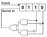
The initial content of the 4-bit serial-in-parallel out, right shift, shift register as shown in figure are 0110. After 3 clock pulses the contents of the shift register will be
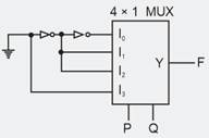
The logic function implemented by the circuit below is (ground implies a logic ‘0’):
Consider the following statements.
A half adder
1. Is a half – subtractor also
2. Has two outputs = x.y and = xy for two inputs x and y.
3. Has two outputs = x+y and = xy for two input x and y.
4. Is a combinational circuit.
Which of the statements given above is/are correct ?
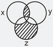
The Boolean expression for the shaded area in the Venn diagram is