Which one of the following effects in the system is NOT caused by negative feedback?
Match List-I with List-II and select the correct answer using the codes given below the lists:
|
List-I |
List-II |
|
A. Mass |
1. Capacitor |
|
B. Damper |
2. Voltage |
|
C. Spring |
3. Resistor |
|
D. Force |
4. Inductor |
The servomotor differs from the standard motors principally in that, it has
For the mechanical system with mass and viscous friction components, shown in the figure, is
The law / principle in mechanical systems, analogous to Kirchhoff’s laws in electrical systems, is
The transfer function of a unity feedback system is , the centroid and breakaway point respectively are:
Negative feedback in a closed-loop control system DOES NOT
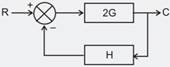
The block diagram of a system is shown below
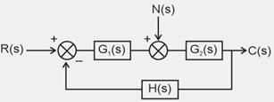
In order to reduce the effect of noise element:
Consider the signal flow graph of a system
of the system is __________
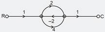
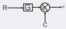
The value of of the following figure is ________.
To convert a given block diagram
To a unity feedback system
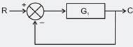
G1 should be
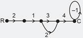
Calculate the transfer function for signal flow graph shown below.
Which one of the following block diagram is equivalent to the below shown block diagram?
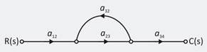
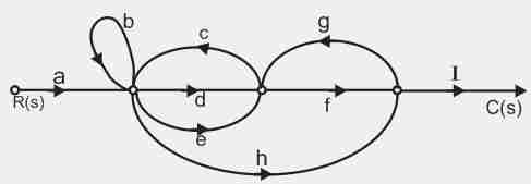
The number of forward paths and the number of non-touching loop pairs for the signal flow graph given in the figure below are, respectively.
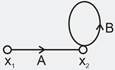
For the signal-flow graph shown in the given figure, the value of x2 is