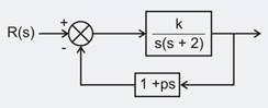
For the system shown in figure, with a damping ratio of 0.7 and an undamped natural frequency of 4 rad/sec, the value of k and p
The unity feedback system shown in fig has
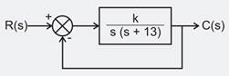
The block diagram shown in figure gives a unity feedback closed loop control system. The steady state error in the response of the above system to unit step is
A second order system has a transfer function given by . It the system initially at rest is subjected to step input at t = 0, the second peak in the response will occur at
For a second order system, damping ration () is 0 < < 1 then the roots of the characteristics polynomial are:
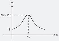
Calculate damping factor for the given resonating frequency response plot having dc gain = 1
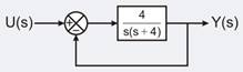
For the second order closed loop system shown in the figure, the natural frequency (in rad/sec) is
How can the steady state error in a system be reduced?
For a second order system which of the following statements are true
I) Resonant frequency is indicative of steady state
II) Resonant peak is indicative of relative stability
III) Resonant frequency is indicative of setting time.
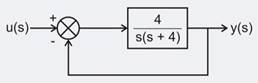
An under damped second order system having transfer function . The frequency response of the system is shown below. Calculate gain k.
Consider a system with the transfer function . Its damping ratio will be 0.5. When the value of k is
A linear time invariant system initially at rest, when subjected to a unit step input, gives a response . The transfer function of the system is
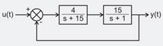
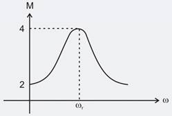
Consider the feedback system shown below which is subjected to a unit step input. The system is stable and has following parameters kp = 4, ki = 10, = 500 and = 0.7. The steady state value of z is
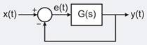
For the unity feedback control system shown in the figure, the open-loop transfer function G(s) is given as
The steady state error ess due to a unit step input is
For the second order closed-loop system shown in the figure, the natural frequency (in rad/s) is